
 EN
EN
 ar
ar bg
bg hr
hr cs
cs da
da nl
nl fi
fi fr
fr de
de el
el hi
hi it
it ko
ko no
no pl
pl pt
pt ro
ro ru
ru es
es sv
sv tl
tl iw
iw id
id lv
lv lt
lt sr
sr sk
sk sl
sl uk
uk vi
vi et
et hu
hu th
th tr
tr fa
fa ms
ms hy
hy ka
ka ur
ur bn
bn mn
mn ta
ta kk
kk uz
uz ku
ku
load cell cable
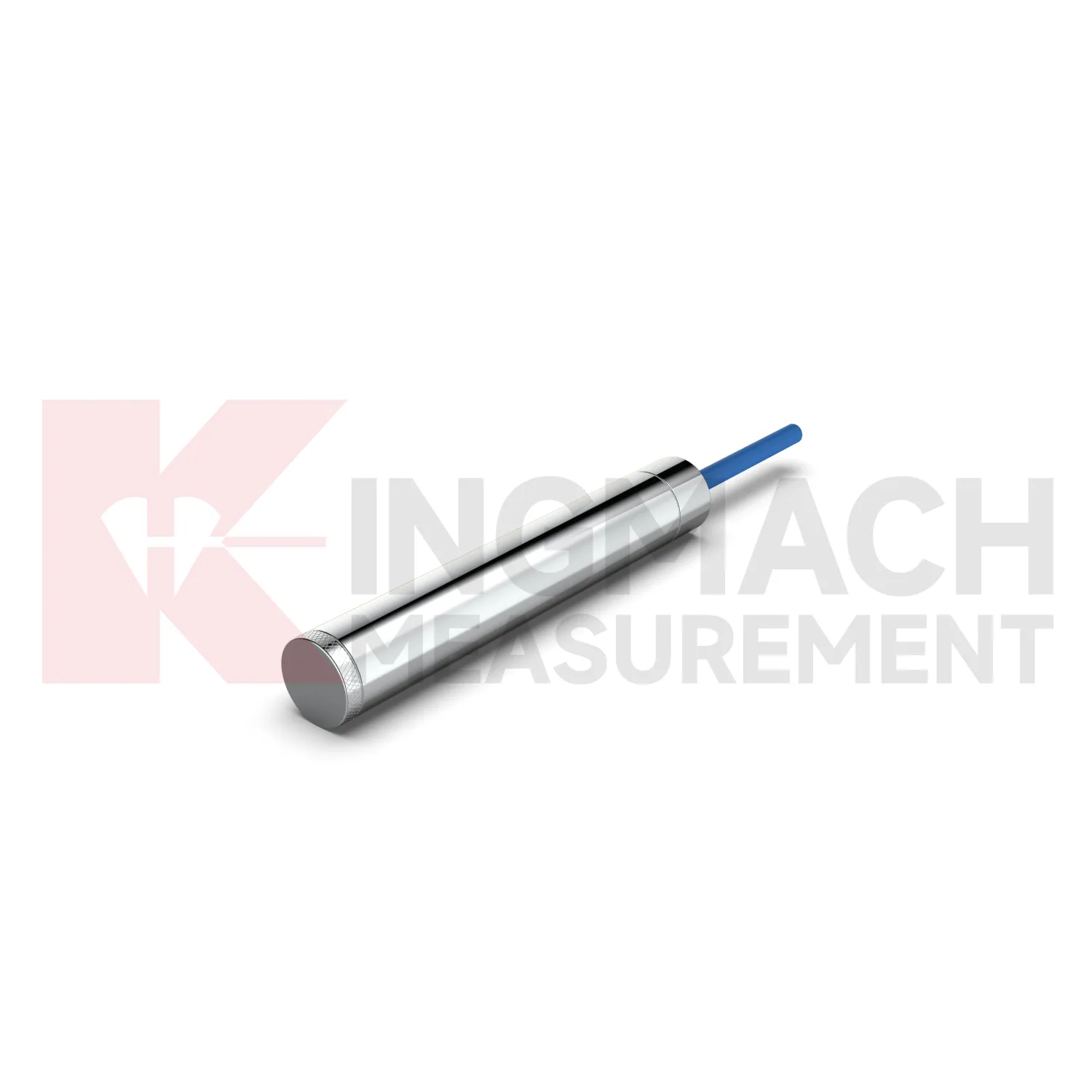
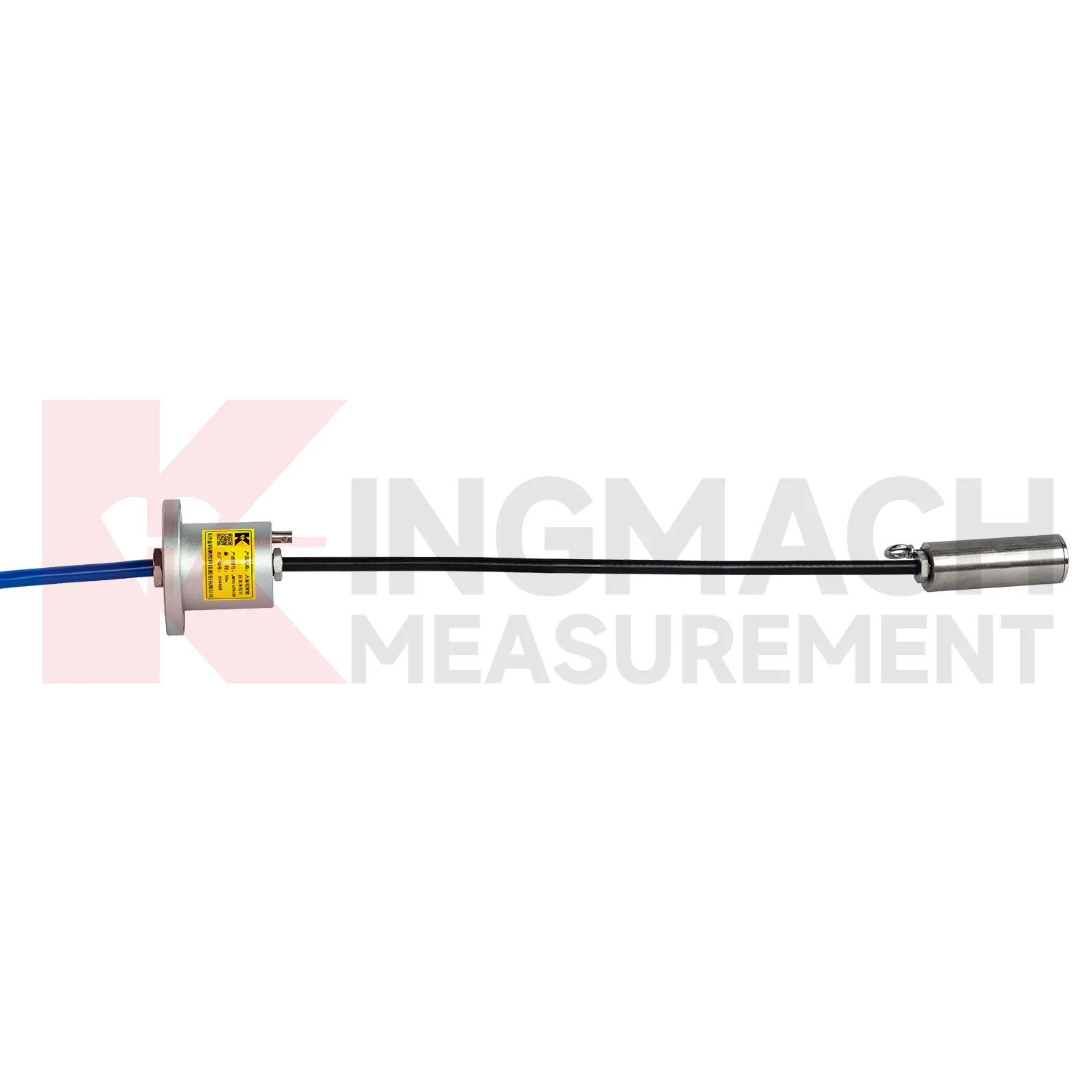
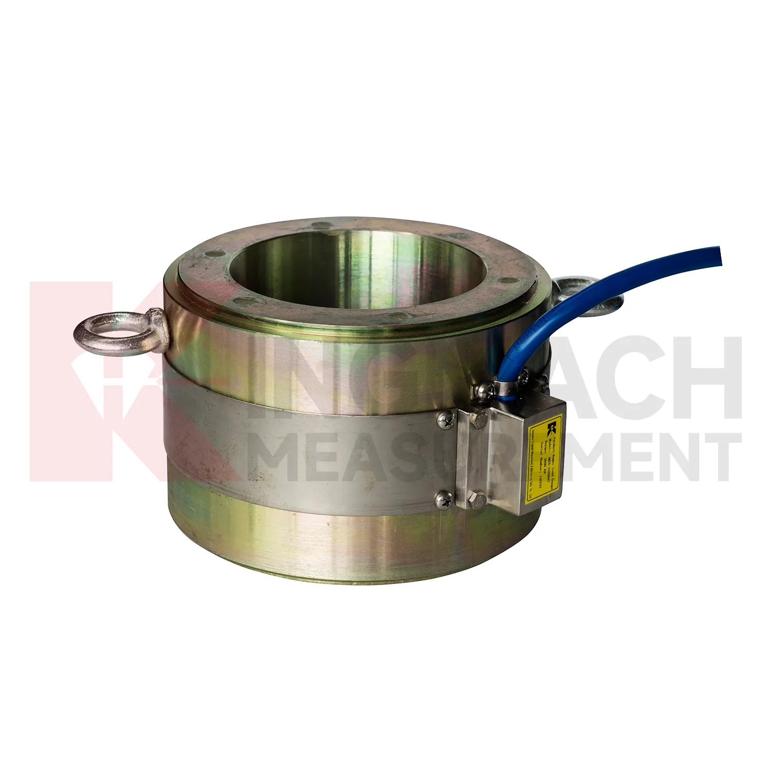
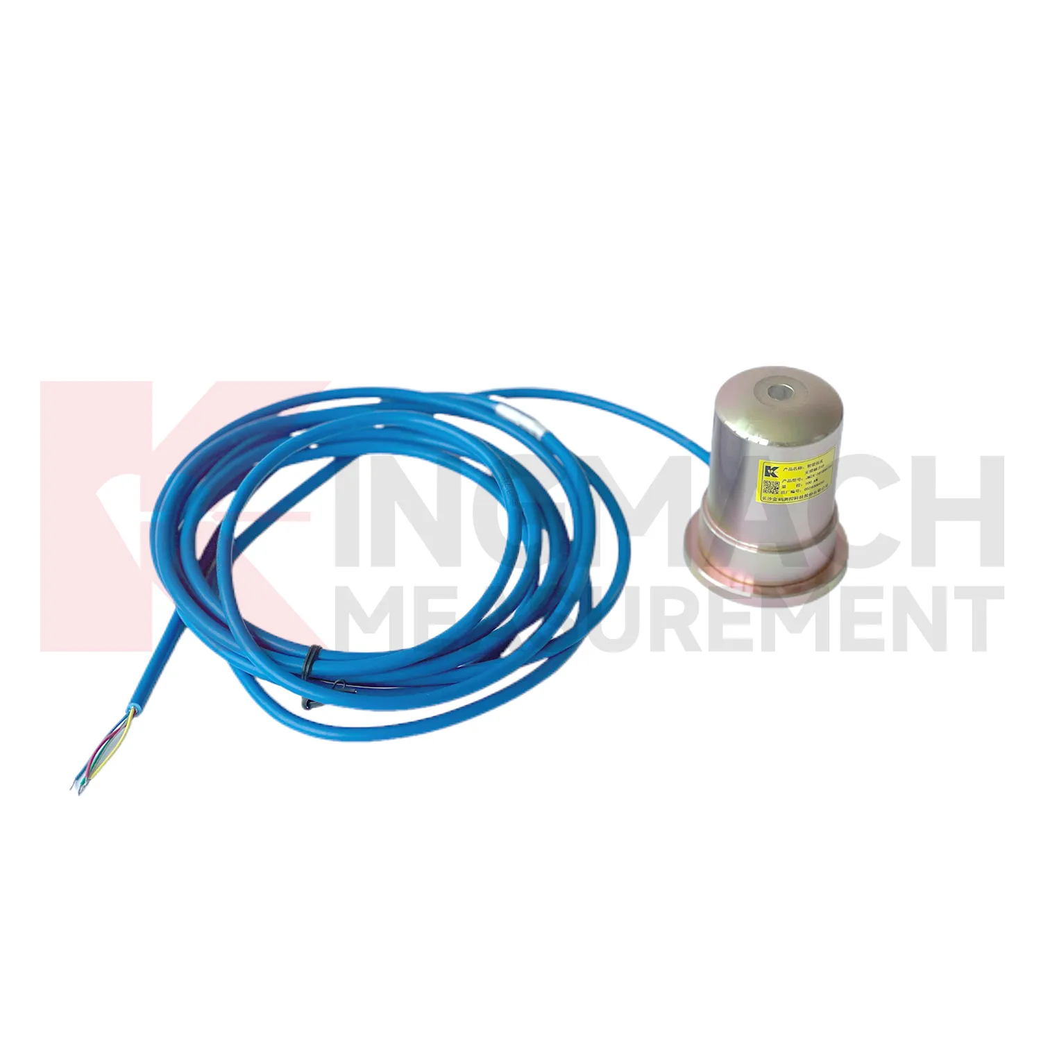
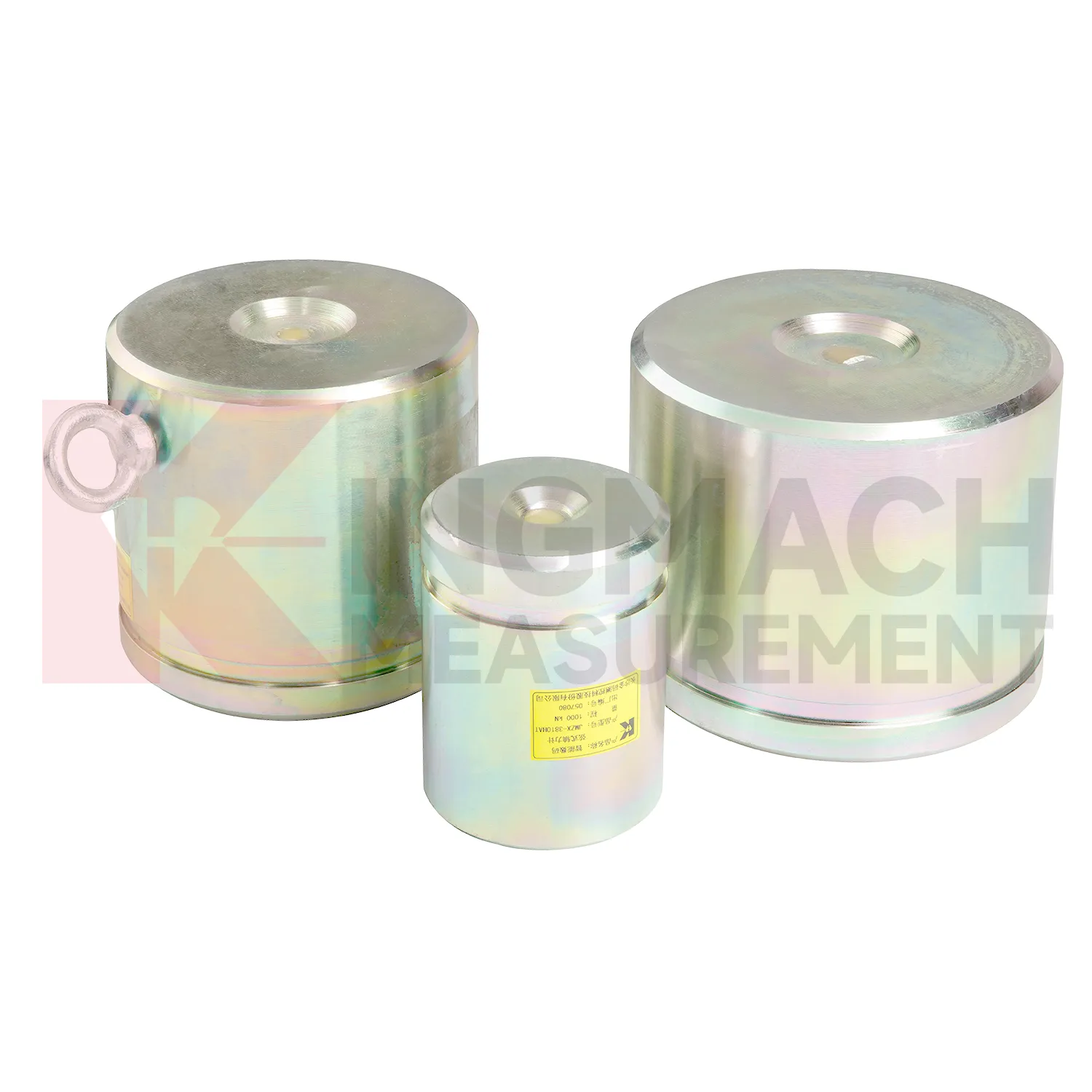
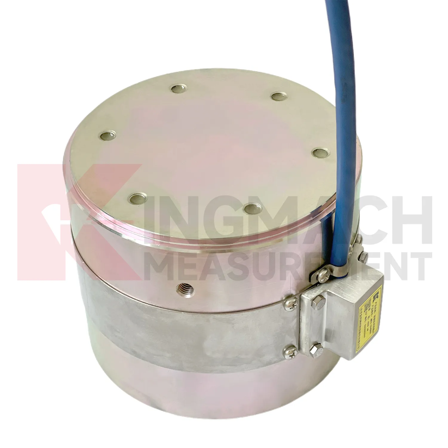
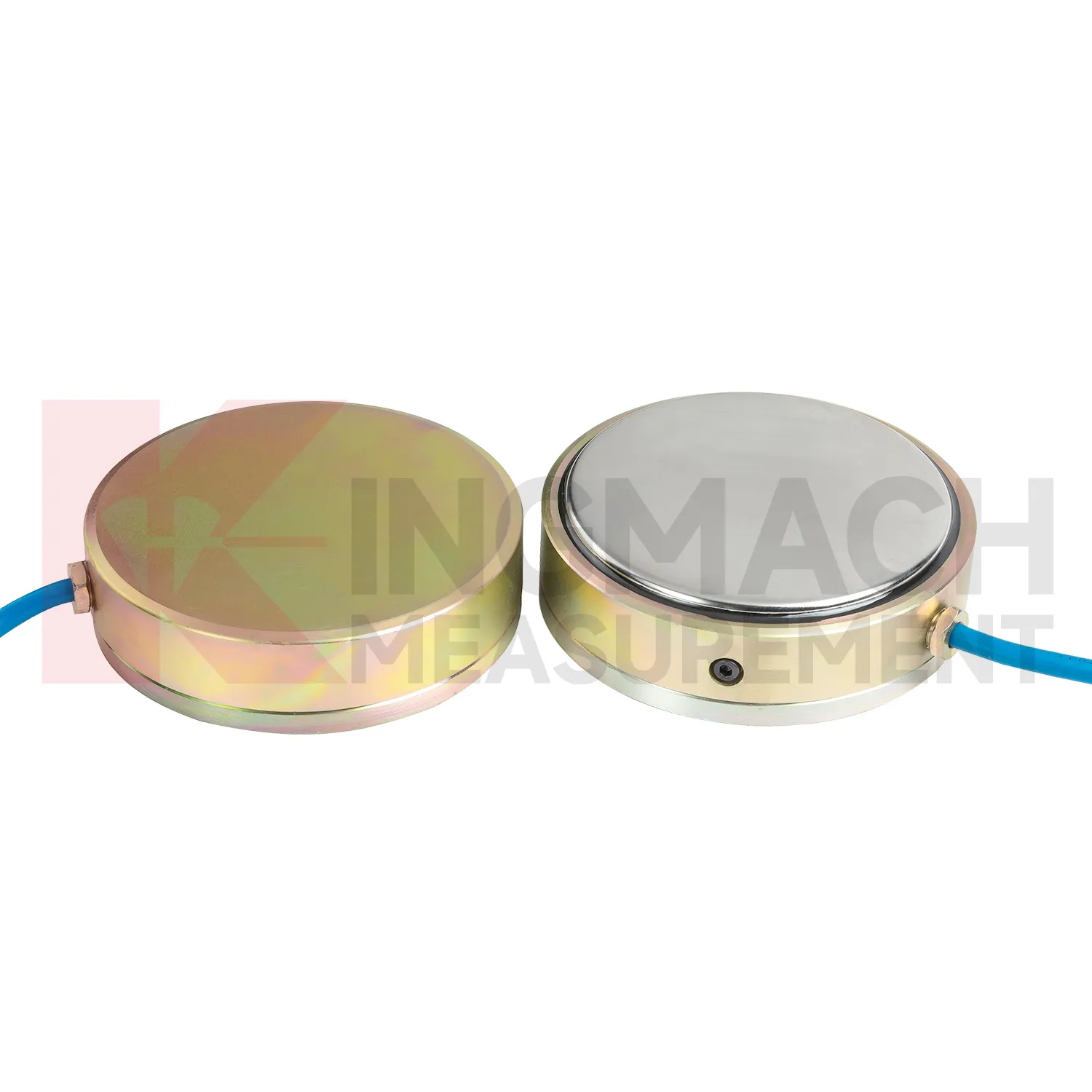
Kingmach load cell cable product information is especially helpful during early engineering review because it gives model families rather than one generic device. The JMZX-3XXXHAT hollow load cell is tied to annular multi-string construction, elastic steel, ultra-high-strength vibrating wires, anchor welding, temperature correction, and 500 kN to 8000 kN ranges. The JMZX-35XXHAT solid load cell is tied to compression monitoring, 1000 kN to 10000 kN ranges, 0.1 kN resolution, and 0.5%FS precision. The JMZX-38XXHAT axial force meter is tied to steel support measurement, 200 kN to 3000 kN ranges, and 1 MPa waterproof performance. Those distinctions guide model selection before purchase. For a bridge, the force path may require hollow or solid construction. For a tunnel support, direct axial force display may be more practical. For soil pressure, MPa range and buried durability matter more than kN capacity. Matching the type to the load path prevents expensive changes after delivery. The product pages also show that standard models and customized versions may exist side by side. That is important because site geometry, force range, and available clearance may require confirmation before the load point can be ordered with confidence. It also gives the contractor clearer limits for installation geometry, cable routing, waterproof protection, and calibration review before the work reaches the field.
Application of load cell cable
In building structural health monitoring, load cell cable can be used around transfer structures, temporary supports, column load checks, foundation testing, and heavy equipment installation areas. The monitoring need is often construction stage control rather than a permanent visible defect. Loads may shift when floors are cast, jacks are released, shoring is removed, or new equipment is placed. Kingmach solid load cells offer 1000 kN to 10000 kN ranges, 0.1 kN resolution, and 0.5%FS precision, with a -30°C to 80°C working temperature range. Axial force meters add direct kN display for steel support points and 0.5%FS accuracy. These parameters help site teams check whether the support path is behaving as planned. The reading should be reviewed together with settlement, tilt, crack gauges, and construction sequence notes. For long term building owners, retaining the original model, calibration coefficient, zero value, and first stable reading makes later inspection far easier when occupancy, equipment load, or renovation changes the load pattern. In buildings, temporary works often disappear after the next construction stage, so the early record should be complete. Photographs of the installed point, bearing plates, cable path, and readout channel can prevent confusion during later structural review.
The future of load cell cable
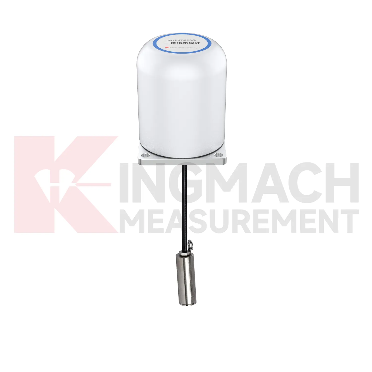
Geotechnical use of load cell cable will become more connected to environmental monitoring. Earth pressure cells with 0.3 MPa to 8 MPa ranges and 0.001 MPa resolution can already record soil or contact pressure, but future value comes from reading pressure with rainfall, groundwater, seepage, settlement, and slope movement. A pressure increase after rain may be acceptable in one slope and worrying in another, depending on the ground model and drainage condition. Digital twins can handle that comparison if the data is clean enough. Kingmach's wider catalog, including piezometers, water level meters, settlement sensors, tiltmeters, data loggers, and visualization software, supports that direction. Wireless communication will help remote slopes and embankments, while wired systems may remain preferable for buried points with long service expectations. Future standards for monitoring reports will likely ask for more traceable context around each reading, including sensor range, accuracy, calibration date, and installation depth. That connection makes trend review more useful after storms.
Care & Maintenance of load cell cable
For load cell cable working in cold, hot, or wet environments, maintenance should use the product parameters as inspection triggers. Solid load cells list a -30°C to 80°C temperature range, while axial force meters list 1 MPa waterproof performance and earth pressure cells list ±0.5°C temperature accuracy. These ratings help, but field practice still matters. During installation, keep connectors dry, avoid sharp cable bends, prevent direct mechanical blows, and secure the instrument away from water pooling where possible. During long term use, inspect after freeze-thaw cycles, heat waves, storms, flooding, and nearby welding or electrical work. Temperature correction should reduce measurement influence, but readings should still be reviewed with the actual site temperature. If a value moves only during daily temperature swings, check the thermal pattern before issuing a structural warning. If a value changes after water exposure, inspect sealing and cable insulation before resetting alarm thresholds. Do not ignore seasonal effects.
Kingmach load cell cable
load cell cable becomes most useful when the project treats it as part of a measurement chain. The chain starts with model selection and calibration, continues through surface preparation, installation, cable protection, readout setup, and first stable reading, then carries on through reporting and maintenance. Kingmach's range includes products with high capacity force measurement, waterproof construction, smart memory, direct kN display, and compatibility with readouts and automated acquisition systems. Those features only pay off when the field record is disciplined. The sensor should be named consistently, protected from mechanical damage, checked after loading events, and compared with nearby monitoring points. A force value that appears unusual should not be accepted or rejected in isolation. It should be checked against temperature, recent work, cable condition, connector sealing, and the last normal trend before a conclusion is made. That same record can later support warranty review, acceptance files, and maintenance planning. This is especially useful when the same point moves from construction control into long term asset monitoring.
FAQ
Q: How can load cell cable be connected to a monitoring platform? A: Use compatible readouts, acquisition modules, data loggers, DTUs, and software platforms according to site access, cable distance, power, and reporting requirements. Q: What makes smart models useful in large networks? A: Stored model data, calibration coefficients, zero values, temperature data, and measurement records reduce confusion across many channels. Q: Should manual readings still be kept? A: Yes, manual checks are useful after installation, maintenance, abnormal alarms, or logger changes. Q: How should alarm limits be set? A: Base them on design stage, sensor range, expected load change, temperature behavior, and nearby monitoring points. Q: What data should be reviewed together with force? A: Settlement, displacement, tilt, water level, pore pressure, rainfall, temperature, construction events, and inspection notes.
Reviews
Joshua Clark
We ordered a full monitoring solution including sensors and data loggers. Everything works seamlessly together. Great supplier!
Daniel Brown
Excellent environmental monitoring sensors. The data is consistent, and the system integrates smoothly with our existing setup.
Latest Inquiries
To protect the privacy of our buyers, only public service email domains like Gmail, Yahoo, and MSN will be displayed. Additionally, only a limited portion of the inquiry content will be shown.
Charlotte***@gmail.comUnited Arab Emirates
Hi, we require instrumentation cables suitable for harsh environments. Could you advise on specifica...
Amelia***@gmail.comSingapore
Hello, I am looking for visualization software for monitoring system data analysis. Please let me kn...
Related product categories
- load cell zero balance
- load cell connection diagram
- load cell recalibration
- load cell testing
- load cell wiring schematic
- calibration load cells
- calibration of load cell theory
- load cell failure
- load cell technology
- strain gauge load cell wiring
- diagram 4 wire load cell wire connection
- load cell accuracy calculation